Each injection product (plastic mold) must first determine its mold opening direction and parting line when designing, to ensure that the core pulling slider mechanism is minimized and the influence of the parting line on the appearance is eliminated.
1. After the mold opening direction is determined, the structure of the product’s ribs, buckles, protrusions and other structures should be designed to be consistent with the mold opening direction as much as possible to avoid core pulling to reduce the stitching line and extend the mold life;
2. After the mold opening direction is determined, the appropriate parting line can be selected to avoid the undercut in the mold opening direction to improve the appearance and performance.
Demolding slope
1. Appropriate stripping angle can avoid product hair (pulling). The release slope of smooth surface should be ≥0.5 degree, the surface of fine skin pattern (sand surface) is greater than 1 degree, and the surface of coarse skin pattern is greater than 1.5 degrees.
2. Appropriate stripping slope can avoid product top injury, such as top white, top deformation, top breaking.
3. When designing deep cavity products, the slope of the outer surface should be greater than the slope of the inner surface as much as possible to ensure that the mold core is not biased during injection, to obtain a uniform product wall thickness, and to ensure the material strength of the product opening.
Product wall thickness
1. All kinds of plastics have a certain range of wall thickness, generally 0.5 ~ 4mm, when the wall thickness exceeds 4mm, it will cause too long cooling time, produce shrinkage and other problems, should consider changing the product structure.
2. Uneven wall thickness will cause surface shrinkage.
3. Uneven wall thickness will cause porosity and welding marks.
Reinforcement
1. The reasonable application of reinforcing ribs can increase product rigidity and reduce deformation.
2. The thickness of the reinforcement must be ≤ (0.5 ~ 0.7) t product wall thickness, otherwise it will cause the surface shrinkage.
3. The slope of one side of the rib should be greater than 1.5 ° to avoid top injury.
Fillet
1. Fillets that are too small may cause stress concentration in the product and cause cracking.
2. If the fillet is too small, it may cause stress concentration in the mold cavity and cause the cavity to crack.
3. The setting of reasonable rounded corners can also improve the processing technology of the mold. For example, the cavity can be directly processed by r cutter milling, while avoiding inefficient electrical processing.
4. Different rounded corners may cause the movement of the parting line. Different rounded corners or clear corners should be selected according to the actual situation.
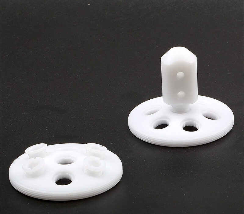
hole
1. The shape of the hole should be as simple as possible, generally round.
2. The axial direction of the hole is consistent with the direction of mold opening, which can avoid core pulling.
3. When the length-to-diameter ratio of the hole is greater than 2, the draft angle should be set. At this time, the diameter of the hole should be calculated according to the small diameter size (maximum physical size).
4. The length-to-diameter ratio of blind holes generally does not exceed 4. Anti-hole punching
5. The distance between the hole and the edge of the product is generally greater than the aperture size.
Core pulling, slider mechanism of injection mold and avoidance
1. When the plastic parts cannot be demolded smoothly according to the direction of mold opening, the core-pulling slider mechanism should be designed. The slider of the core pulling mechanism can form a complex product structure, but it is easy to cause defects such as product stitching and shrinkage, and increase the cost of the mold and shorten the life of the mold.
2. When designing injection products, if there are no special requirements, try to avoid core pulling structure. If the axial direction of the hole and the direction of the rib are changed to the direction of mold opening, the method of cavity core penetration is used.
One-piece hinge
1. Using the toughness of pp material, the hinge can be designed to be integrated with the product.
2. The size of the film as a hinge should be less than 0.5mm, and it should be kept uniform.
3. When injection molding an integrated hinge, the gate can only be designed on one side of the hinge.
Insert
1. Inserting inserts into injection products can increase local strength, hardness, dimensional accuracy and set small threaded holes (shafts) to meet various special needs. At the same time will increase product costs.
2. The insert is generally copper, or other metal or plastic parts.
3. The part of the insert that is embedded in the plastic should be designed with anti-rotation and anti-pull-out structures. Such as: knurling, hole, bending, flattening, shaft shoulder, etc.
4. The plastic around the insert should be properly thickened to prevent stress cracking of the plastic.
5. When designing the insert, you should fully consider its positioning method in the mold (hole, pin, magnetic)
Deduction
1. The buckle device is designed to be shared by multiple buckle positions at the same time, so that the overall device will not be unable to operate due to the damage of individual buckle positions, thereby increasing its service life, and then adding more rounds to increase the strength.
2. Tolerance of the relevant dimensions of the buckling position is very strict. Too many reverse positions are likely to cause damage to the buckling position. On the contrary, if there are too few reverse positions, the assembly position is difficult to control or the assembly part is too loose. The solution is to reserve a way to easily change the mold to add glue to achieve.
Welding (hot plate welding, ultrasonic welding, vibration welding)
1. Welding can improve the connection strength.
2. The use of welding can simplify product design.
327Views

The advantages and disadvantages of 3D printing prototype spray paint and UV highlight treatment
In the process of making 3D printing models, some products with high appearance requirements often need to be spray painted...
Factors affecting the price of beryllium copper
International economic situation. The correlation between the commodity market and the economic situation is obvious, especially as the world economy...

How to determine the thickness of aluminum alloy die castings
In the design process of aluminum alloy die castings, many customers are uncertain about the thickness of aluminum alloy die...
Precision CNC machining manufacturers explain how CNC CNC lathes are processed
According to the introduction of precision CNC machining manufacturers, the large-scale CNC machining parts are made of bar materials, and...
Talking about the Application of Beryllium Copper in Plastic Mould
Talking about the Application of Beryllium Copper in Plastic Mould Nowadays, more and more beryllium copper mold materials have...