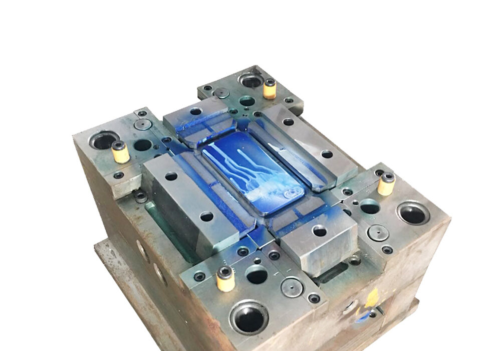
The basic knowledge of the mold is to tell the basic composition of the mold, the influence of the shape on the product, and the introduction of the mold model.
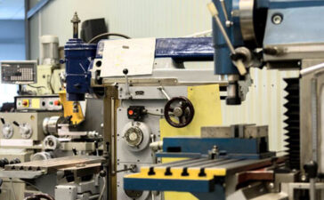
1. The basic composition of the mold
- (1) Front mold (main mold) (fixed mold)
- (2) Rear mold (outer mold) (movable mold)
- (3) Inlay block (inlay block)
- (4) Ranking (slider)
- (5) Slanted top
- (6) Thimble
- (7) Gate (water inlet)
2. Influence of mold product shape on product
Wall thickness, geometry, will affect forming shrinkage, draft angle
3. The effect of water intake on product shrinkage
When the size of the water inlet is large, the shrinkage rate is small; when the size of the water inlet is small, the shrinkage rate is large, the direction of the water flow is parallel, the shrinkage rate is large, and the vertical direction is small.
Some people say that after I analyze the product structure, I can start designing the mold. The answer is of course no. If you want to avoid detours during the design process, some items that affect the mold structure must be confirmed. The details are as follows:
- The tonnage and model of the injection molding machine used by the customer. This confirmation is not good. Unable to determine the entrance diameter of the mold gate sleeve and the diameter of the retaining ring. The position, and the depth of the injection molding machine into the mold, even the size of the mold frame, the closing height and so on. You have worked hard to design a mold structure with a cylindrical core. You also have a sense of accomplishment. The mold cannot be produced by the customer. Because customers only have electric injection molding machines, and there are no extra neutrons, it is estimated that you will feel crying.
- The coding method of the customer’s injection molding machine, commonly used are pressure plate coding mold, screw coding method, hydraulic coding method, magnetic coding method, etc. This confirmation is good, you know that you don’t need to design a pattern screw hole or code slot when designing a mold.
- The problem of the product we just analyzed, as well as product clamping, product material and shrinkage rate. Don’t take it for granted that the shrinkage of pp plastics must be 1.5%, which must be confirmed with the customer to understand the grade they are ultimately used for production, whether any modified materials are added, etc.
(1) In order to ensure the strength and rigidity of the product without thinning the wall thickness of the plastic parts, ribs can be provided at appropriate parts of the plastic parts to prevent deformation. In some cases, the plastic flow problem during the forming process can be improved.
(2) The thickness of the ribs should not exceed 50% of the plastic parts, generally around 20%.
(3) The rib should be lower than the plane of the plastic part
4. Hole
- (1) Welding marks are easily generated around the hole, which reduces the strength of the plastic parts. Note that the distance between holes and holes, and between holes and plastic parts should generally be greater than twice the hole.
- (2) The edge of the hole can be used to strengthen the strength of the hole
- (3) The depth of the blind hole cannot exceed 4 times the aperture
- (4) The screw holes should pay special attention to the strength and size of the holes. If the hole diameter is too large, the screw may slip after insertion. If the aperture is too small, you cannot insert screws or screw columns.
- (5) The hole column is too long (high) should pay attention to poor die arrangement
- (6) The depth of the aperture should not exceed 8 times the aperture
- (7) Stepped holes, the core is fixed on both sides of the fixed mold and the movable mold, the concentricity is difficult to guarantee, and the junction of the two cores is prone to burrs, so under the guidance of the other end, either side (aperture ) The core is increased by more than 0.5mm
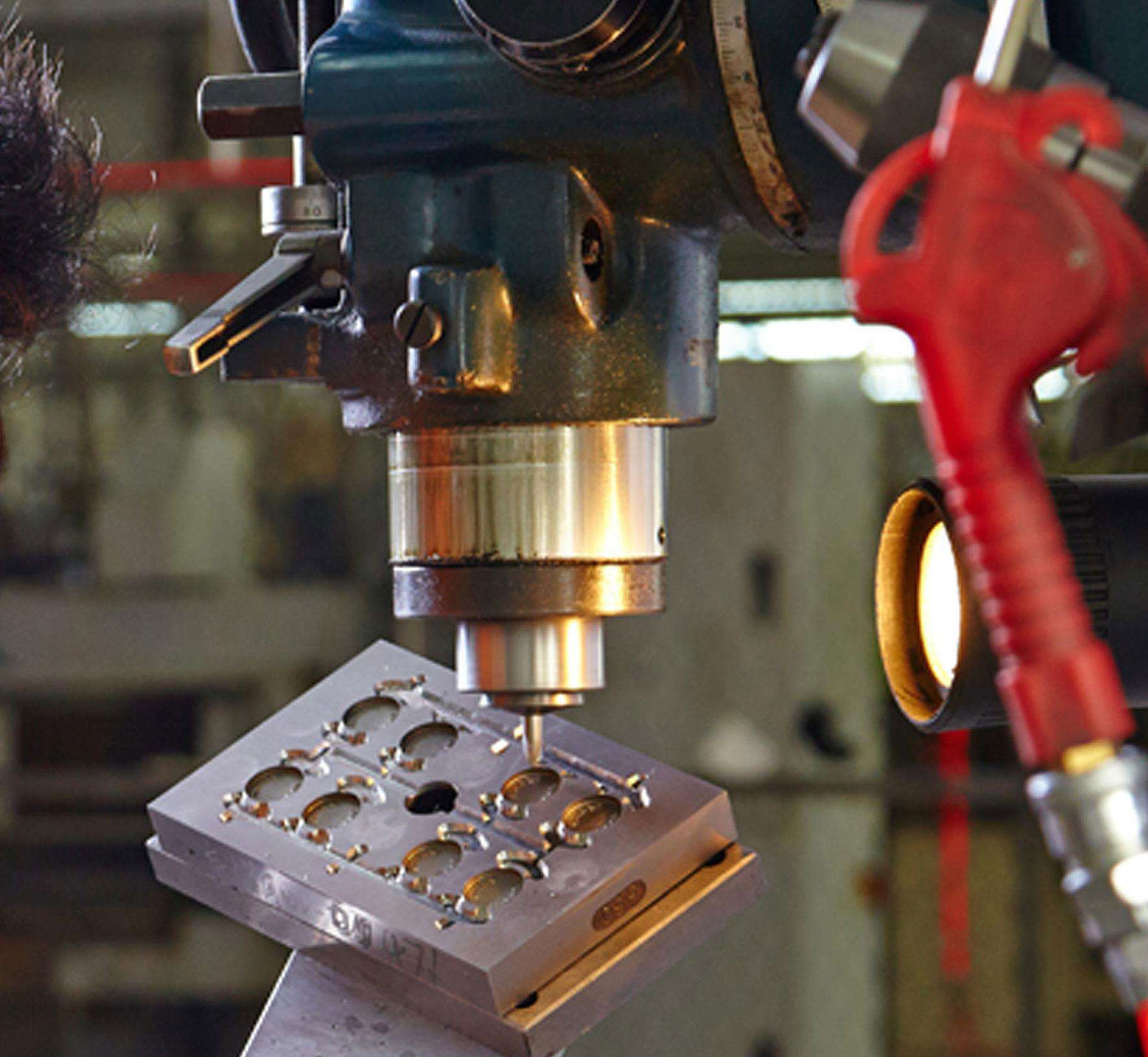
5. Mold insert, row position, slanted top
The inserts, rows, and pitched tops of the mold are usually mounted on the moving mold of the mold. If the joint is not tight, there will be burrs.
Only by understanding the customer’s requirements before designing can you have a predictable design for the waterway oil circuit. When you work hard to design the mold, you will find that the customer needs to connect the oil circuit to the inside of the mold. Then you change it, it is estimated that you will be half tired, because your waterway, ejector, screws are not easy to arrange. The design sequence of these four paths is to first ensure the oil path, because the oil path should be evenly distributed, especially the mold structure that the cylinder needs to eject. If the oil circuit is unbalanced, the action of the cylinder will continuously pop up. lost balance.
Of course, gear oil separators can also be used, but this is more complicated. The second is the waterway, because the waterway needs to ensure the cooling effect, uneven distribution will affect product quality and mold life. Finally, the gas circuit and circuit. The order of placement on the mold is that the circuit closest to the top is the water circuit and the air circuit, and the bottom is the tubing connector.
