In order to ensure that the mold can produce qualified products, ensure the service life of the mold, meet the production and use requirements of product design, and put into normal production. This specification recognizes the mold standards in terms of product quality, mold structure, process requirements of injection molding plants, etc., and evaluates the mold quality accordingly;
Guideline:
- GB / T 12554-2006 Technical conditions of plastic injection mould
- GB / T 4169.1 ~ 4169.23-2006 injection mold parts
- GB / T 12556-2006 plastic injection molding frame technical conditions
- GB / T 14486-2008 Dimensional tolerance of plastic molded parts
The appearance, size and fit of the molded product
- 1. No defects are allowed on the surface of the product: lack of material, charring, blushing, peaking, blistering, blushing (or cracking, breaking), baking, wrinkling.
- 2. Weld seam mark: the length of the general round perforated weld seam is not more than 5mm, and the length of the special-shaped perforated weld seam is less than 15mm. The strength of the weld can be tested by functional safety.
- 3. Shrinkage: The appearance of the surface is not allowed to shrink, obviously it is not allowed to shrink slightly (the hand does not feel dents).
- 4. Variations: Generally, the flatness of small products is less than 0.3mm, which requires assembly requirements to ensure assembly.
- 5. The appearance is obvious, there should be no air particles or flowers, and the product should generally not have bubbles.
- 6. The geometric shape and dimensional accuracy of the product should meet the requirements of a formal and effective drawing (or 3D file). The product tolerance is based on the tolerance principle, the shaft tolerance is negative tolerance, and the hole size tolerance is positive tolerance. base on needs.
- 7. Product wall thickness: The product wall thickness generally requires an average wall thickness. The non-average wall thickness should meet the drawing requirements. According to the characteristics of the mold, the tolerance should be -0.1mm.
- 8. Product matching: shell bottom shell: surface deviation is less than 0.1mm, no shaving phenomenon, holes, shafts, surfaces with matching requirements should ensure matching intervals and use requirements.
The appearance of the mold
- 1 The mold nameplate has complete content, clear writing and neat arrangement.
- 2 The nameplate should be attached to the mold feet near the template and the reference corner. The nameplate is fixed and not easy to fall off.
- 3 According to customer requirements, the cooling nozzle should be a plastic block nozzle.
- 4 The cooling nozzle should not protrude from the surface of the mold frame.
- 5 The cooling nozzle needs to be processed with a countersink. The diameter of the countersunk hole is 25 mm, 30 mm and 35 mm, respectively. The chamfering of the orifice should be consistent.
- 6 The cooling nozzle should have entrance and exit signs.
The English characters and numbers of the - 7 mark should be greater than 5/6, and the position should be 10 mm directly under the spout. Handwriting should be clear, beautiful, neat and evenly spaced.
- 8 Mold parts should not affect the lifting and storage of the mold. There should be exposed cylinders, faucets, pre-reset mechanisms, etc. during installation and should be protected by legs.
- 9 outriggers should use screws to fix it to the template, and the overly long outriggers can be fixed to the template by machining externally threaded columns.
- 10 The size of the injection hole should meet the requirements of the specified injection molding machine. Except for small molds, only one center cannot be ejected.
- 11 The positioning ring should be fixed and reliable. The diameter of the ring is 100 mm and 250 mm. The positioning ring is 10 ~ 20 mm higher than the bottom plate. Unless otherwise requested by the customer.
- 12 The size of the mold should meet the requirements of the prescribed injection molding machine.
- 13 Install the mold according to the direction requirements. The installation direction should be indicated by the arrow on the front or rear formwork. There should be the word “upward” next to the arrow. The arrow and text are yellow and the height is 50 mm.
- 14 The surface of the template must not have pits, rust, excess rings, water vapor, oil holes and other defects that affect the appearance.
- 15 The mold should be easy to lift. Do not disassemble the mold parts during the lifting process. The lifting ring must not interfere with the water nozzle, cylinder and pre-reset lever.
Mold material and hardness
The mold template should be a standard template that meets the standards.
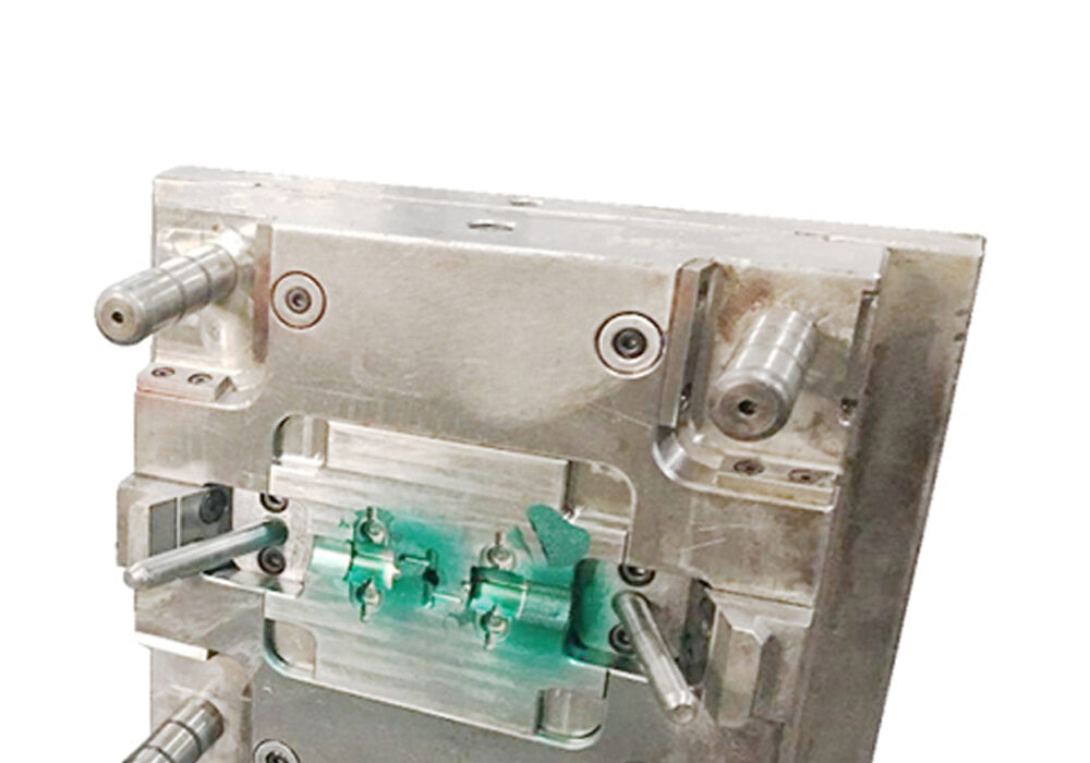
Molded parts, parting surfaces, exhaust slots
- 1 The surface of the front and rear molds must not have irregularities, pits, rust and other defects.
- 2 The insert is matched with the mold base, and the fillet gap is less than 1mm.
The - 3 parting surfaces are kept clean and tidy, there is no portable grinding wheel, to avoid the entry of air, and there is no depression in the sealing part.
- 4 The depth of the exhaust slot should be less than the overflow value of the plastic.
- 5 Plug-in research and development is in place, stable placement and reliable positioning.
- 6 Inserts, inserts, etc. should be firmly positioned and fixed, round pieces should stop, and copper and iron pieces should not be placed under the inserts.
- 7 The end of the jack is consistent with the core.
- 8. The front and rear modules have no defects such as undercut and chamfering.
- 9 The ribs should be loosened smoothly.
- 10 multi-cavity mold products, the left and right parts are symmetrical and should be marked with L or R. If the customer has requirements on the location and size, it should meet the customer’s requirements, generally added in a place that does not affect the appearance and assembly, and the font size is 1/8. Yes.
- 11 The locking surface of the mold base should be in place and will encounter more than 75% of the area.
- 12 The hammer should be close to the side wall, close to the ribs and bosses, and use a larger hammer.
- 13 For the same piece, the numbers 1, 2, 3, etc. should be indicated.
- 14 Each contact surface, insertion surface and parting surface should be in place.
- 15 parting surface sealant should meet the design standards. Medium-sized molds are 10-20 mm, large-sized molds are 30-50 mm, and the rest are machined to avoid air ingress.
- 16 Skin and sandblasting should meet customer requirements evenly.
- 17 For products that require appearance, the screws on the product should be prevented from shrinking.
- 18 The top of a spiral column with a depth of more than 20 mm should be used.
- 19 The product wall thickness is uniform, the deviation is controlled within ± 0.15mm.
- 20 ribs should be less than 60% of the wall thickness of the outer surface.
- 21Insert blocks on the inclined roof and slider should be firmly fixed.
- 22 Insert the front mold into the front mold or the rear mold into the front mold. The surrounding mold should be locked and machined with slopes to avoid air ingress.
The temperature difference between the temperature setting table and the actual displayed temperature should be less than ± 5 ℃, and the temperature control is sensitive.
- Cavity and nozzle mounting holes should be perforated.
- The hot runner wiring should be bundled and covered with a pressure plate.
- There are two sockets of the same size, which should be clearly marked.
- The control wire should be sheathed and not damaged.
- The temperature control cabinet has a reliable structure and no loose screws.
- The socket is installed on the bakelite and cannot exceed the maximum size of the template.
- Wire should not be exposed outside the mold.
- All hot runners or templates should have rounded corners where they come into contact with the wires.
Before the 20 template is assembled, there is no open circuit or short circuit on all lines. - All wiring connections are correct and the insulation performance is good.
- After clamping the template, check all the pipes again with a multimeter.